Part 2: Aircraft Composite Repair
Module 2.1: Fundamentals of Advanced Composite Materials
Advanced composite materials have largely replaced traditional aluminum alloys in modern commercial and military aircraft structures (such as the Boeing 787 and Airbus A350) due to their high strength-to-weight ratio, superior fatigue resistance, and immunity to conventional atmospheric corrosion.
A structural composite material consists of two primary elements: high-strength reinforcement fibers embedded within a protective resin matrix.
1. Structural Reinforcement Fibers
Reinforcement fibers carry the structural load applied to the aircraft component. The three most common structural fibers used in aviation are:
A. Carbon / Graphite Fiber (CFRP)
- Characteristics: Extremely high tensile strength and stiffness; low thermal expansion.
- Aviation Applications: Primary structural members (fuselage barrels, wing skins, vertical stabilizers).
- Precautions: Carbon is electrically conductive. Direct contact with aluminum promotes galvanic corrosion; therefore, a fiberglass barrier ply is required between carbon and aluminum interfaces.
B. Fiberglass (GFRP)
- Characteristics: Lower cost, high impact resistance, non-conductive (radar transparent).
- Aviation Applications: Radomes, fairings, floor panels, and control surface trailing edges.
- Common Grades: E-Glass (Electrical grade, general purpose) and S-Glass (Structural grade with ~40% higher tensile strength).
C. Kevlar / Aramid (AFRP)
- Characteristics: Exceptional toughness, high impact resistance, vibration damping, and flame resistance.
- Aviation Applications: Engine nacelles, wing leading edge panels, cargo liner containment panels.
- Precautions: Absorbs moisture rapidly if unsealed. Difficult to drill without special brad-point or diamond-coated bits as fibers tend to fuzz.
2. Matrix Systems (Resin & Hardener)
The matrix holds the fibers in alignment, transfers shear loads between fiber plies, and protects the fibers from abrasion and chemical attack.
- Epoxy Resins: The primary thermosetting matrix used in structural aircraft repair due to high mechanical strength and excellent adhesion to carbon and aramid fibers.
- Mixing Ratio: Epoxy systems require strict stoichiometric mixing ratios (e.g., $100 : 25$ by weight). Deviances greater than $\pm 2\%$ can severely compromise structural integrity.
- Pre-impregnated Materials (Prepregs): Fabrics pre-impregnated with uncured resin system at the factory.
- Storage Requirement: Must be stored in deep freezers at $0^\circ\text{F}$ [$-18^\circ\text{C}$] or colder to prevent premature polymerization (out-time limits apply when removed from cold storage).
3. Core Materials & Sandwich Construction
Composite structures generally fall into two construction categories: Monolithic (Solid Laminate) and Sandwich Panel Construction.
Sandwich panels utilize lightweight core materials bonded between two thin, rigid composite facesheets (skins) to provide high bending stiffness with minimal weight gain.
Common Core Types
- Nomex / Aramid Honeycomb: Paper-like aramid fibers dipped in phenolic resin. Extremely lightweight and common in flight control surfaces and floor panels.
- Aluminum Honeycomb: Used in high-stress, high-temperature applications (e.g., flap surfaces, engine nacelles).
- Balsa Wood & Rigid Foam (PVC/ROHACELL): Used in fairings, radomes, and secondary structural panels.
4. Technical Specifications & Metric/Imperial Conversion Reference
When preparing composite materials, core replacements, and repairs, strict dimensional tolerances apply:
| Parameter / Dimension | Imperial Measurement | Metric Measurement | Aviation Standard Application |
| Typical Single Ply Thickness | $0.005”$ – $0.010”$ | [0.127 mm – 0.254 mm] | Standard carbon/epoxy dry or prepreg ply thickness |
| Nomex Honeycomb Cell Size | $1/8”$ – $3/8”$ | [3.18 mm – 9.53 mm] | Standard core cell openings for sandwich structures |
| Nomex Core Thickness | $0.250”$ – $0.500”$ | [6.35 mm – 12.70 mm] | Typical elevator/rudder trailing edge core thickness |
| Fiber Glass Isolation Ply | $0.003”$ – $0.005”$ | [0.076 mm – 0.127 mm] | Galvanic barrier between CFRP skin and aluminum fittings |
| Storage Temperature (Prepreg) | $0^\circ\text{F}$ | [-18^\circ\text{C}] | Maximum storage temp for uncured prepreg shelf-life |
Module 2.2: Composite Damage Inspection & Nondestructive Testing (NDT)
Unlike metallic structures, where fatigue cracks and external deformation are often visible to the naked eye, composite structures can sustain severe internal damage without displaying significant exterior indication. This phenomenon—known as Barely Visible Impact Damage (BVID)—requires specialized inspection methods to detect sub-surface structural failures before repair execution.
1. Common Types of Composite Damage
Before selecting an inspection method, technicians must understand the two primary modes of sub-surface composite degradation:
A. Delamination
- Definition: The separation of adjacent plies (layers) within a solid laminate panel or facesheet.
- Primary Cause: Low-velocity impacts (e.g., dropped tools, runway debris, hail) that induce out-of-plane shear stress.
- Structural Effect: Severely reduces the compressive strength and flexural rigidity of the laminate.
B. Debonding
- Definition: The physical separation of a composite facesheet from an underlying core structure (such as Nomex honeycomb or foam), or the separation of a bonded stiffener/doubler from the skin.
- Primary Cause: Core crushing, inter-laminar shear stress, or moisture ingress breaking down the adhesive line.
2. Tap Testing (Acoustic Impact Testing)
Tap testing is the most widely used field technique for quick, preliminary detection of voids, delaminations, and core debonding near the surface.
- Tooling: A specialized light-weight tapping hammer or a small coin (e.g., $0.078”$ to $0.125”$ [2.0 mm to 3.2 mm] thick disk).
- Procedure: Tap the composite surface lightly along a grid pattern, listening for changes in acoustic response:
- Clear / Sharp Ring: Indicates a solid, well-bonded structural laminate.
- Dull / Hollow Thud: Indicates an internal void, delamination, crushed core, or debonded skin.
- Limitations: Highly subjective (depends on inspector hearing) and effective only for shallow defects down to approximately $0.100”$ [2.54 mm] in thickness.
3. Ultrasonic NDT Methods
Ultrasonic testing (UT) uses high-frequency sound waves (typically $2.25\text{ MHz}$ to $5.0\text{ MHz}$) transmitted through the material to detect internal acoustic impedance changes caused by flaws.
A. Ultrasonic Display Types
- A-Scan: A 1D signal showing pulse-echo signal amplitude against depth/time. Refracted peaks indicate exact defect depth from the surface.
- B-Scan: A 2D cross-sectional view of the part, providing depth profile mapping along a linear scan path.
- C-Scan: A 2D plan view mapping of the structure, providing a top-down graphic representation of the defect size, boundary, and location.
B. UT Inspection Modes
- Pulse-Echo Mode: Uses a single transducer that acts as both transmitter and receiver. Sound reflects off internal delaminations or the back wall. Requires access to only one side of the aircraft panel.
- Through-Transmission Mode: Uses two aligned transducers positioned on opposite sides of the panel. A drop in received signal indicates an internal blockage/defect. Requires access to both sides of the panel.
4. Infrared Thermography
Thermography evaluates thermal variations across a composite structure using an infrared camera system.
- Operating Principle: Heat energy is applied to the surface (Active Thermography). Solid composite material conducts heat evenly, whereas air gaps caused by delamination or debonding act as thermal barriers, causing localized surface temperature anomalies (“hot spots” or “cold spots”).
- Key Advantage: Allows rapid, contactless inspection of large surface areas (such as elevator panels, radomes, or wing skins).
5. Summary Table: Inspection Methods Comparison
| Inspection Method | Target Defect Type | Depth Capability | Single-Side Access? | Primary Field Advantage |
| Tap Testing | Shallow delamination, skin-to-core debonding | Up to $0.100”$ [2.54 mm] | Yes | Low cost, portable, fast preliminary check |
| Ultrasonic A-Scan | Deep delaminations, voids, thickness check | Up to $0.500”$ [12.70 mm]+ | Yes (Pulse-Echo) | Accurate depth measurement |
| Ultrasonic C-Scan | Complete 2D boundary of internal damage | Full laminate thickness | Yes / No | High-resolution defect mapping |
| Thermography | Debonding, water ingress in honeycomb core | Up to $0.150”$ [3.81 mm] | Yes | Rapid inspection of large air |
Module 2.3: Scarf Repairs, Ply Alignment, Vacuum Bagging & Hot Bonder Curing
Restoring the structural strength and smooth aerodynamic contour of a damaged composite panel requires precision scarf machining, exact ply orientation matching, uniform vacuum consolidation, and controlled thermal curing.
1. Scarf Joint Geometry & Taper Calculations
A scarf repair involves gradually tapering the parent laminate around the damaged area to create a smooth, shallow taper slope. This maximizes shear bond area and allows repair plies to transfer tensile and compressive loads evenly through load paths.
Scarf Taper Ratio Standard
- Structural Standard: Most Structural Repair Manuals (SRMs) specify a scarf taper ratio between 20:1 and 50:1, with 30:1 being the standard for primary structural laminates.
- Taper Ratio Calculation:$$\text{Scarf Length / Radius } (L) = \text{Laminate Thickness } (t) \times \text{Scarf Ratio}$$
Calculation Example (Imperial & Metric)
For a damaged carbon fiber skin panel with a thickness ($t$) of $0.120”$ [3.05 mm] using a 30:1 scarf ratio:
- Imperial:$$\text{Scarf Length } (L) = 0.120” \times 30 = \mathbf{3.600”}$$(The taper extends $3.600”$ outwards from the edge of the cutout radius).
- Metric:$$\text{Scarf Length } (L) = 3.05\text{ mm} \times 30 = \mathbf{91.50\text{ mm}}$$
2. Ply Orientation & Layup Sequence
Composite plies are highly directional (anisotropic). To restore $100\%$ structural strength, each repair ply must match the exact warp thread direction and fiber angle of the original parent ply it replaces.
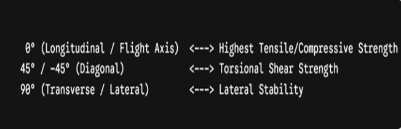
- Orientation Identification: Use a warp clock or optical magnifying glass to determine original ply angles ($0^\circ, \pm45^\circ, 90^\circ$).
- Extra Cover Ply (Cap Ply): SRM procedures typically require one additional sacrificial cover ply extending $0.500”$ [12.70 mm] beyond the outer scarf perimeter to protect the joint and allow flush sanding.
3. Vacuum Bagging Layup Schedule
Vacuum bagging applies uniform atmospheric pressure across the repair patch, extracting trapped air and excess resin while consolidating plies during cure.
Standard Layup Sequence (Bottom to Top):
- Parent Structure / Scarf Area: Prepared and solvent cleaned.
- Structural Film Adhesive: Applied directly to the scarfed surface.
- Replacement Composite Plies: Stacked matching original ply orientations.
- Peel Ply: Porous nylon or Teflon fabric that leaves a clean, etchable finish for painting after removal.
- Perforated Release Film: Allows air and controlled resin flow to pass through.
- Bleeder / Breather Cloth: Non-woven synthetic fabric that absorbs excess resin and maintains an open air path for vacuum extraction.
- Thermocouples (J-Type/K-Type): Temperature sensors placed near the repair perimeter.
- Silicone Heat Blanket: Electric heating element powered by the hot bonder.
- Outer Breather Cloth: Protects the vacuum bag from sharp heater edges.
- Vacuum Bagging Film & Sealant Tape (Tacky Tape): Airtight envelope sealed to the panel surface.
Vacuum Pressure Check
- Target Vacuum Level: A minimum of $22.0\text{ inHg}$[558.8\text{ mmHg} / 74.5\text{ kPa}]$ mercury vacuum pressure must be drawn before applying heat.
- Vacuum Leak Check: Disconnect vacuum source for 5 minutes; maximum allowed vacuum drop is $1.0\text{ inHg}$[25.4\text{ mmHg}]$ per 5 minutes.
4. Hot Bonder Curing Profile
A digital Hot Bonder unit controls the silicone heat blanket and monitors thermocouples to execute a precise temperature cure profile.
Standard Cure Cycle Parameters
| Cycle Phase | Parameter Standard (Imperial) | Parameter Standard (Metric) | Technical Requirement / Purpose |
| Vacuum Minimum | $22.0\text{ inHg}$ | [558.8 mmHg / 74.5 kPa] | Maintain continuous throughout entire cure profile |
| Ramp-Up Rate | $2^\circ\text{F}$ to $5^\circ\text{F}$ per minute | [1.1^\circ\text{C} to 2.8^\circ\text{C} per min] | Prevents thermal shock and volatilizes trapped solvents |
| Dwell / Cure Temp | $250^\circ\text{F} \pm 10^\circ\text{F}$ (or $350^\circ\text{F}$) | [121^\circ\text{C} \pm 5.5^\circ\text{C} / 177^\circ\text{C}] | Cross-links epoxy matrix (per SRM specification) |
| Hold Time | $60$ to $120\text{ minutes}$ | [60 to 120 minutes] | Full polymer matrix cross-linking |
| Ramp-Down Rate | Max $5^\circ\text{F}$ per minute down to $140^\circ\text{F}$ | [Max 2.8^\circ\text{C}/min down to 60^\circ\text{C}] | Prevents thermal cracking and residual stress build-up |
Module 2.4: Sandwich Core Repair & Facesheet Patch Installation
Sandwich panels derive their rigidity from the bond between thin, strong facesheets and a lightweight honeycomb core. When damage penetrates the outer skin and crushes or contaminates the core, technicians must systematically remove the failed material, replace or pot the core, and rebuild the facesheet to restore structural margin.
1. Damage Removal & Core Preparation
Before repairing the core, all compromised material and fluid contamination must be excised without damaging the opposite skin.
- Routing the Damaged Skin: Cut out the damaged facesheet over the core using a router, dremel tool, or skin saw. Keep cutout shapes circular or rectangular with a minimum corner radius of $0.500”$ [12.70 mm].
- Removing Damaged Core: Carefully excavate crushed, delaminated, or corroded core material down to the inner skin using hand tools or an end mill.
- Drying Fluid Contamination: Honeycomb cells frequently trap water, hydraulic fluid, or jet fuel.
- Perform a moisture check using thermal imaging or a vacuum test.
- Dry out moisture in a vacuum bag setup at $140^\circ\text{F}$ to $160^\circ\text{F}$ [60^\circ\text{C} to 71^\circ\text{C}] before applying repair resins.
2. Core Repair Methods: Potting vs. Core Splicing
The method selected to restore core integrity depends on the damage diameter ($D$) specified in the Structural Repair Manual (SRM).
Method A: Core Potting (Minor Damage)
- Application: Used for small, localized damage where the core damage diameter is typically $\le 1.000”$ [25.40 mm] (or as restricted by the SRM).
- Process: Fill the excavated cavity with a low-density Syntactic Foam potting compound (epoxy resin mixed with microballoons).
- Cure & Sanding: Cure the potting compound according to manufacturer instructions, then sand it completely flush with the surrounding undisturbed core surface.
Method B: Core Plug Splicing (Major Damage)
- Application: Required when damage exceeds potting limits—typically for core damage diameter $> 1.000”$ [25.40 mm].
- Core Matching: Fabricate a replacement core plug from identical material (e.g., Nomex or Aluminum), matching cell size, density, and thickness ($t$).
- Ribbon Direction (L-Direction): Align the ribbon direction (the strongest axis of the honeycomb cells) of the core plug to match the ribbon direction of the parent panel.
- Foaming Adhesive Application: Wrap the perimeter of the core plug with structural expanding foaming adhesive (e.g., $250^\circ\text{F}$ [121^\circ\text{C}] or $350^\circ\text{F}$ [177^\circ\text{C}] curing film). During heat cure, the adhesive expands up to 200–300%, filling cell walls and bonding the plug securely to the surrounding core.
3. Facesheet Patch Installation & Structural Layup
Once the core is restored and sanded flush, the damaged facesheet must be rebuilt using either a Step Repair or Scarf Repair method.
- Film Adhesive Placement: Apply a layer of structural film adhesive over the exposed core and repair perimeter to ensure maximum peel strength between the core and new composite plies.
- Ply Stacking & Orientation: Lay down structural replacement plies matching original ply orientations ($0^\circ, \pm45^\circ, 90^\circ$).
- Extra Cover Ply: Install an additional sacrificial cover ply extending $0.500”$ [12.70 mm] beyond the repair edge to allow flush sanding.
- Vacuum & Heat Cure: Vacuum bag the assembly to a minimum of $22.0\text{ inHg}$[558.8\text{ mmHg} / 74.5\text{ kPa}]$ and execute the SRM-specified thermal cure cycle using a silicone heat blanket and hot bonder.
4. Technical Summary Table: Core Repair Guidelines
| Repair Parameter | Core Potting Method | Core Plug Splicing Method | Aviation Standard / SRM Limit |
| Damage Limit (Diameter) | $\le 1.000”$ | $> 1.000”$ | [$\le 25.40\text{ mm}$ for Potting] |
| Primary Material | Syntactic Epoxy Compound | Matching Nomex/Aluminum Core | Identical cell size, density & thickness |
| Splicing Adhesive | N/A (Potting compound acts as filler) | Expanding Foaming Adhesive | Expands during thermal cure cycle |
| Core Ribbon Alignment | N/A | Must match parent core $L\text{-direction}$ | Restores structural shear capability |
| Vacuum Pressure Minimum | $22.0\text{ inHg}$ | $22.0\text{ inHg}$ | [558.8 mmHg / 74.5 kPa] during cure |