Part 1: Aircraft Sheet Metal Repair
Module 1.1: Foundations & Structural Materials
Understanding the fundamental alloys, structural classifications, and metallurgical treatments is mandatory before performing any structural repair. Every sheet metal modification must maintain or restore the original structural integrity defined by the aircraft manufacturer.
1. Aircraft Structural Aluminum Alloys & Properties
Pure aluminum is lightweight and corrosion-resistant, but lacks the tensile strength required for heavy structural loads. Aircraft structures rely on aluminum alloys—blending aluminum with elements like copper, zinc, magnesium, and manganese to achieve high strength-to-weight ratios.
Key Aluminum Alloys Used in Aviation
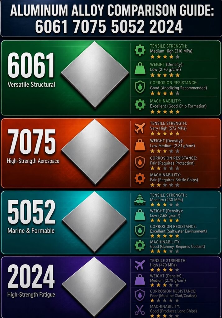
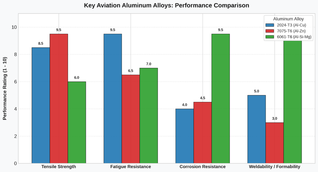
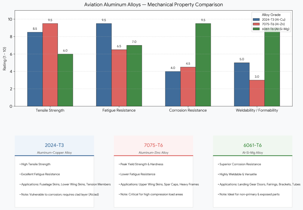
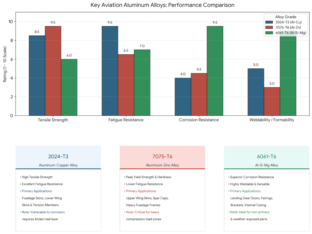
| Material Quality | 2024-T3 (Aluminum-Copper Alloy) | 7075-T6 (Aluminum-Zinc Alloy) | 6061-T6 (Aluminum-Silicon-Magnesium Alloy) |
| Tensile Strength | High (470 M Pa) | Very High (572 M Pa) | Medium – High (310 M Pa) |
| Weight | Medium (2.78g/cm3) | Low-Medium (2.81g/cm3) | Low (2.70g/cm3) |
| Corrosion Resistance | Poor (Must be Clad/Coated) | Fair (Requires protection) | Good (Anodizing Recommended) |
| Machinability | Good (Produces long chips) | Fair (Harder and brittle chips) | Excellent (Good chip formation) |
2. Structural Member Classification: Primary vs. Secondary
Aircraft structures are divided into three structural categories based on how critical flight safety and load distribution.
| Structural Category | Definition | Key Examples | Failure Impact |
| Primary Structure | Carries major flight, ground, or pressurization loads. | Wing spars, fuselage frames, pressure bulkheads, skin panels. | Direct risk of catastrophic structural failure or loss of control. |
| Secondary Structure | Carries localized aerodynamic loads or transfers loads to primary members. | Wing ribs, control surfaces (elevators/ailerons), fairings. | Localized damage, minor aerodynamic penalty, non-catastrophic. |
| Tertiary / Auxiliary | Non-load-bearing internal fittings or cosmetic elements. | Floor panels, internal brackets, equipment racks. | No immediate effect on flight safety. |
3. Heat Treatment, Temper Designations & Cladding
Temper Designations
The letter following the alloy number specifies how the metal was mechanically or thermally processed:
- -O: Annealed (softest, highly ductile state for complex forming operations).
- -F: As fabricated (no specific thermal control).
- -T3: Solution heat-treated, cold-worked, and naturally aged to a stable state (e.g., 2024-T3).
- -T6: Solution heat-treated and artificially aged in an oven for maximum strength (e.g., 7075-T6).
Cladding (Alclad)
High-strength alloys like 2024 contain copper, making them vulnerable to intergranular corrosion. To prevent this, manufacturers apply Alclad—a thin layer of pure aluminum (approx. 2.5% to 5% of total sheet thickness) rolled onto both sides of the core alloy sheet.
Technician Warning: When sanding or cleaning Alclad sheets prior to repair, never use coarse abrasives or steel wool. Removing the pure aluminum clad layer exposes the core alloy to rapid galvanic and environmental corrosion.
Module 1.2: Structural Inspection & Damage Assessment
Accurate damage assessment is the critical link between discovering a structural defect and executing an approved repair. A technician must properly classify the defect, measure its dimensions against Structural Repair Manual (SRM) guidelines, and determine whether the structure can remain in service, be blended out, or requires a formal structural patch.
Key Maintenance Documentation
- AMM (Aircraft Maintenance Manual): Gives instruction in which all maintenance tasks carried out on an aircraft shall be accomplished. This includes items such as lubrication, functional check, servicing, parts removal and installation and usually includes some structural repairs and modifications.
- SRM (Structural Repair Manual): Contains procedures for evaluations and repairs of structural damages found on an aircraft. It also includes part numbers of structural items. When no applicable procedures is available in SRM for you found structural damage it is necessary to contact the OEM for specific repair instructions.
- IPC (Illustrated Parts Catalogue): Composed of diagrams and parts list, can be found the assembly of parts with the listed part numbers. This is highly used in conjunction with the AMM to identify parts.( Example: The scuff plate removal and installation can be found on the AMM, but the part numbers of the scuff plates and screws are in the IPC.)
- CML (Consumable Material List): Approved consumable part numbers such as sealants, primers, cleaning agents and paint for codes ( Ex M2M1000) of consumables listed in other manuals such as AMM, CMM and SRM.
- CMM (Component Maintenance Manual): Detailed maintenance procedures for off-aircraft removable components such as doors, radom, flaps, primary and secondary flight controls. In a repair details can be found in the IPC and can be found allowable damage limits and repairs for this components.
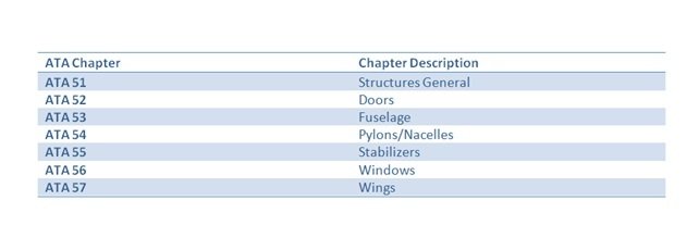
SRM Chapters as follows,
1. Types of Structural Damage
Sheet metal structures experience distinct forms of damage depending on environmental exposure, stress concentrations, and foreign object impacts:
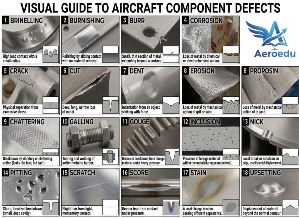
- Scratch / Gouge: A sharp line defect caused by mechanical abrasion. Scratches involve minimal metal displacement, whereas gouges remove material and leave sharp stress risers.
- Dent: A smooth, continuous depression in the sheet metal caused by impact (e.g., ground support equipment or hail). The metal is deformed without puncture or cracking.
- Crack: A partial or complete separation of metal grain structures caused by cyclic fatigue or stress concentration. Cracks always require immediate corrective action.
- Distortion / Buckling: Permanent wave-like deformation across a skin panel or structural frame, indicating that the member was subjected to loads exceeding its yield strength.
2. Structural Repair Manual (SRM) & Allowable Damage Rules
Before attempting any sheet metal work, technicians must consult SRM Chapter 51 (Standard Practices and Structures) and the specific ATA chapter corresponding to the damaged component.
Damage Categories Defined in the SRM:
- Allowable Damage:
- Damage within the limits published in the SRM that does not compromise structural integrity.
- Action: Document location on the aircraft Dent & Buckle chart; no immediate structural repair needed (may require cosmetic blending or monitoring).
- Repairable Damage:
- Damage exceeding allowable limits, but within limits that can be restored using standard SRM repair procedures (e.g., Flush or Overlap patch repairs).
- Action: Perform an approved SRM repair procedure.
- Non-Repairable (Replacement Required):
- Damage exceeding maximum SRM repair limits or affecting primary fatigue-critical members where a field patch is not authorized.
- Action: Replace the structural component or obtain an engineering disposition (e.g., Airbus RAS or Boeing RDAS).
3. Corrosion Identification & Classification
Corrosion is the electrochemical deterioration of metal. In aluminum sheet metal structures, identifying the exact type and severity of corrosion dictates the required removal depth and surface treatment.
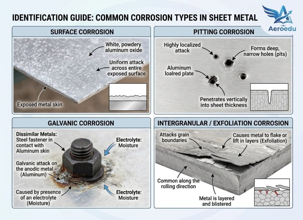
Common Corrosion Types in Sheet Metal
Types of damage and defects that may be observed on aircraft parts are defined as follows:
Corrosion Severity Levels & Assessment
| Corrosion Level | Surface Appearance | Thickness Loss Limits | Recommended Action |
| Level 1 (Light) | Localized white powder, minor surface discoloration. | 10% of original sheet thickness (t) | Light hand sanding, chemical conversion (Alodine), primer re-application. |
| Level 2 (Moderate) | Blistering paint, visible pitting, minor flaking. | 10% – 25% of original sheet thickness (t) | Mechanical blend-out (1:20 or 1:30 taper ratio), depth check, SRM evaluation. |
| Level 3 (Severe) | Deep pits, severe exfoliation, structural cracking. | 25% of original sheet thickness (t) | Material removal exceeding allowable limits; requires structural doubler/patch repair or part replaceme |
Module 1.3: Fasteners, Clecos & Tooling
Precision riveting requires a thorough understanding of fastener selection, temporary clamping tools, pneumatic driving equipment, and flush surface preparation techniques. Executing high-quality structural joints depends on matching the correct fastener alloy and head style to the application and installing it with calibrated tooling.
1. Aircraft Rivets & Fastening Systems
Solid shank rivets, high shear fasteners and lockbolts are basically for joining load-bearing sheet metal structures.
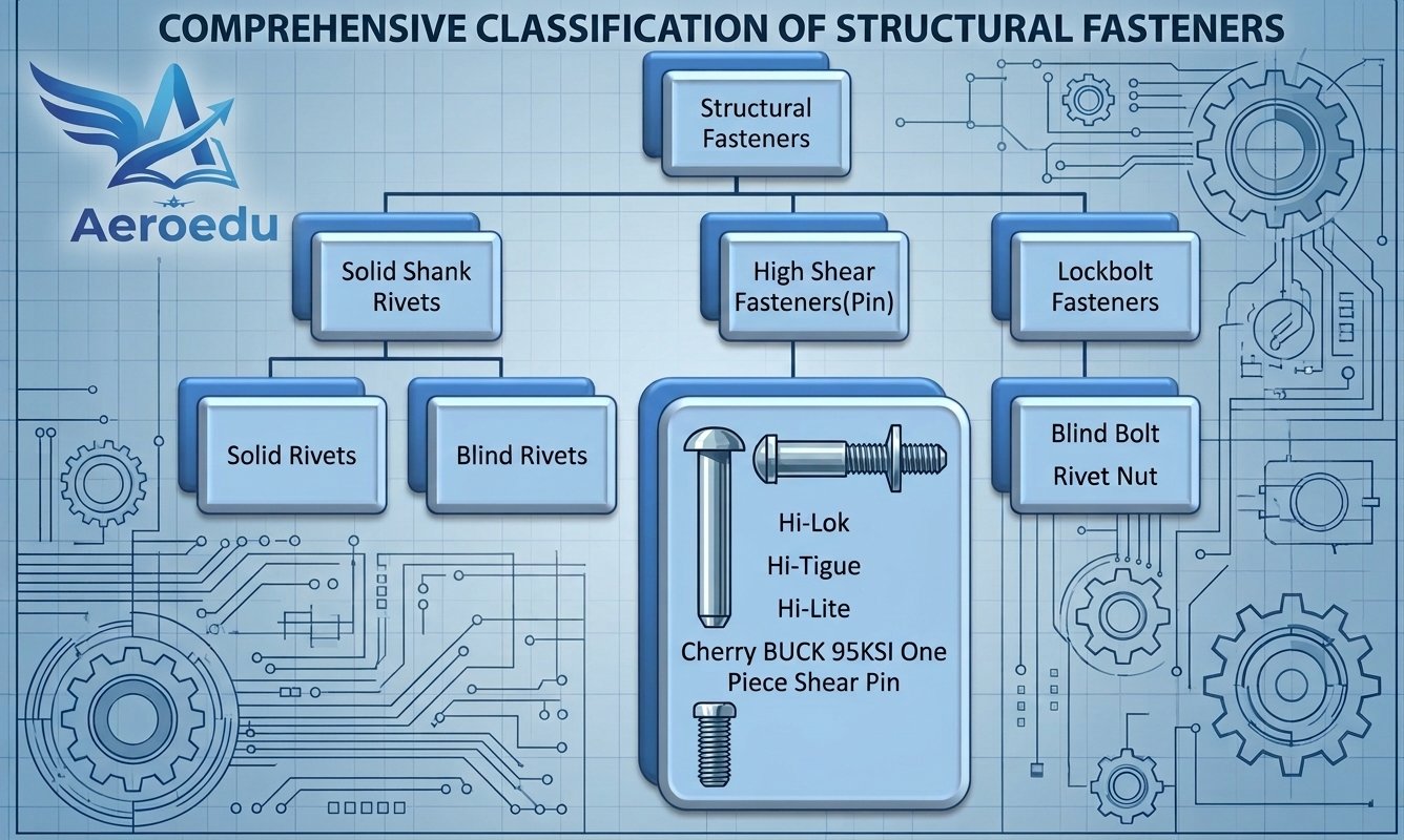
Head Styles(Solid rivets)
- Universal Head (MS20470 / AN470): Features a raised, rounded crown used on internal structural members and non-aerodynamic exterior surfaces.
- Flush / Countersunk Head (MS20426 / AN426): Features a flat head with a 100 degrees bevel, designed to fit into a countersunk or dimpled hole for smooth aerodynamic surfaces.
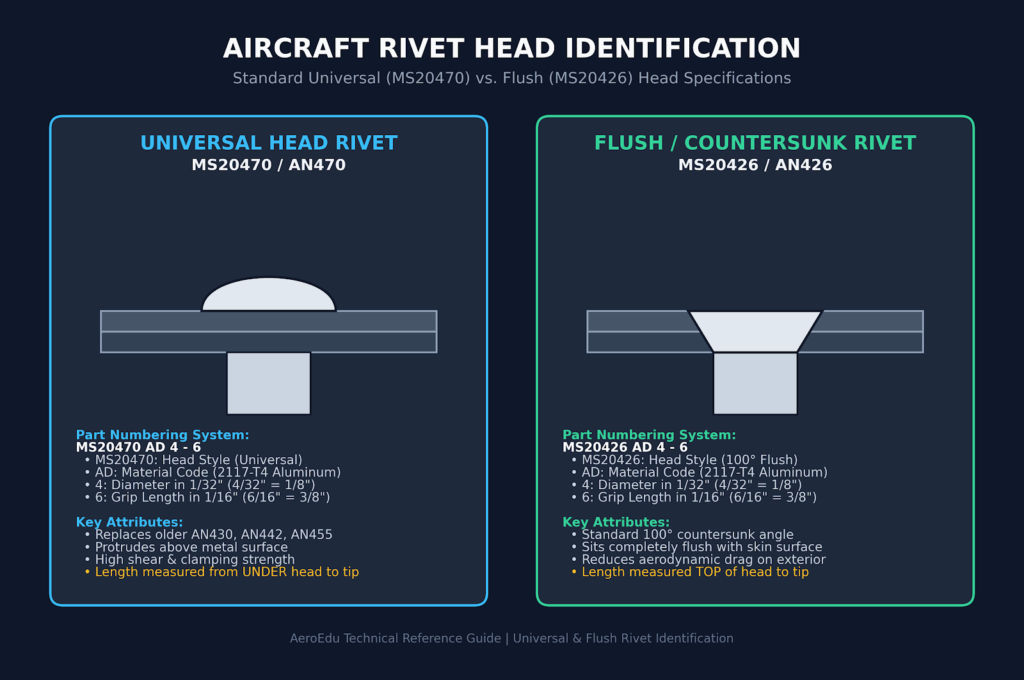
Rivet Alloys & Markings
Solid rivets are color-coded and marked with head symbols (dimples, raised dashes, cross markings) to identify their material composition:
| Alloy Code | Material / Temper | Head Marking | Shear Strength | Driving Condition |
| AD | 2117-T4 (Al-Cu) | Dimple in center | ~26,000 psi | Driven as received (Field standard). |
| D | 2017-T4 (Al-Cu) | Raised teat | ~30,000 psi | “Icebox” rivet (requires solution heat treat). |
| DD | 2024-T4 (Al-Cu) | Two raised dashes | ~34,000 psi | “Icebox” rivet (high strength application). |
| B | 5056-H32 (Al-Mg) | Raised cross | ~28,000 psi | Used exclusively on Magnesium structures. |
| E | 7050-T73 (Al-Zn) | Raised ring | ~33,000 psi | High-strength structural Applications. |
Blind Rivets
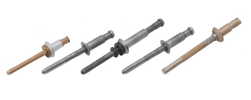
This special designed blind rivets are used to no access area fore other solid rivets. It has been designed to a very special design it is function according to the mechanical system. These rivets are available in three head types. Those head types are used according to the requirements. Head types are follows,
- Universal Head
- 100 degree countersunk head
- 100 degree reduced shear head
2. Temporary Fasteners: Cleco Fasteners
Clecos are spring-loaded, reusable temporary fasteners installed with Cleco pliers. They hold sheet metal panels, doublers, and patches in precise alignment during drilling, deburring, and final riveting.
Cleco Color Coding System
| Cleco Color | Diameter (Inches & [mm]) | Corresponding Drill Bit Size |
| Zinc (Silver) | 3/32” (0.0938”) [2.38 mm] | #40 drill bit |
| Copper | 1/8” (0.1250”) [3.18 mm] | #30 drill bit |
| Black | 5/32” (0.1562”) [3.97 mm] | #21 drill bit |
| Brass (Gold) | 3/16” (0.1875”) [4.76 mm] | #10 drill bit |
3. Driving Equipment: Pneumatic Rivet Guns & Bucking Bars
Forming a structural shop head requires controlled pneumatic impacts paired with an appropriately sized bucking bar.
- Pneumatic Rivet Gun: Sized by piston stroke length (2X, 3X, 4X). A 2X gun is suitable for small rivets (3/32” to 1/8”), while a 3X or 4X gun is used for larger structural rivets (5/32” to 1/4”).
- Rivet Sets: Formed steel bits that fit into the rivet gun nozzle. Must match the head contour (straight or offset for universal heads, flat with rubber guard for flush heads).
- Bucking Bar: High-density steel block (or tungsten carbide) held firmly against the rivet shank. The mass of the bar reflects kinetic energy back into the shank, expanding it into the hole and forming the shop head.
Driven Shop Head Dimensions
A properly driven shop head must satisfy standard structural specifications:
Shop Head Height= 0.5D
Shop Head Width or Diameter= 1.5D
(where D is the nominal shank diameter).
4. Hole Preparation: Countersinking vs. Dimpling
Flush head rivets (MS20426) require a 100 degrees bevel in the top sheet so the rivet head sits flush with the aerodynamic skin profile. The method used depends entirely on the thickness of the sheet metal (t).
Machine Countersinking
- Rule: Permissible only when the top sheet thickness (t) is greater than the depth of the rivet head. A rule of thumb requires the top sheet thickness to be at least 1.5 times the rivet head depth to maintain a cylindrical knife-edge-free hole.
- Tooling: Performed using a microstop countersink cutter with a pilot bit matching the hole diameter.
Dimpling (Press or Coin Dimpling)
- Rule: Required when the top sheet is too thin to machine countersink without enlarging the hole into a sharp knife-edge.
- Process: The metal around the hole is mechanically forged/stretched into a $100^\circ$ cone using male and female dies in a pneumatic squeezer or squeezer set.
- Coin Dimpling: Uses a coin die setup where pressure is applied to the metal around the hole under high force, yielding precise, flush fitments without cracking the material perimeter.
Module 1.4: Repair Calculations & Layout Design
Before cutting metal or drilling holes for a structural repair patch or replacement panel, a technician must perform precise layout calculations. Ensuring correct fastener spacing prevents sheet tear-out and joint failure, while accurate bend calculations guarantee that formed sheet metal components match the exact engineering dimensions specified in the Structural Repair Manual (SRM).
1. Fastener Spacing Calculations
Proper fastener layout distributes structural loads evenly across the repair patch and prevents premature joint failure, stress concentrations, or edge splitting.
Edge Distance (ED)
Edge Distance is the distance from the center of a fastener hole to the nearest edge of the sheet metal plate.
Minimum ED = 2 D
Standard ED = 2 D to 2.5 D
Maximum ED = 4 D
(where D is the nominal diameter of the rivet shank).
- Too close 2D Risk of the fastener tearing through the edge of the sheet (edge shear failure).
- Too far 4D The metal skin edge may lift or pucker between fasteners, allowing moisture ingress and corrosion.
Rivet Pitch (Spacing within a Row)
Rivet Pitch is the distance between the centers of adjacent rivets in the same row.
Minimum Pitch = 3 D
Standard Pitch = 6 D to 8 D
- Rule: Standard structural repairs typically utilize a pitch of 4 D to 8 D
Transverse Pitch (Row Spacing)
Transverse Pitch is the perpendicular distance between parallel rows of rivets in multi-row lap or doubler joints.
Standard Transverse Pitch = 0.75 Rivet Pitch (approximately 4 D to 5 D)
2. Sheet Metal Bending Terms & Geometry
When forming angles or channel sections, sheet metal stretches along the outer bend radius and compresses along the inner bend radius. The Neutral Axis is the theoretical plane within the sheet thickness where no tension or compression occurs.
- Thickness (t) The sheet metal thickness.
- Bend Radius (R): The inside radius of the bend (measured on the inside surface).
- Bend Angle (theta): The degree of angle through which the metal is bent (e.g., 90 degrees).
- Mold Line: The imaginary line formed by extending the flat exterior surfaces past the radius.
- Mold Line Distance (MLD): The distance from an edge to the intersection of the mold lines.
3. Bend Allowance (BA) Formula
Bend Allowance (BA) is the length of material along the neutral axis consumed in forming the bend. Calculating BA determines the total flat pattern width before bending.
Standard Empirical Formula (90 degrees Bends):
BA = (0.01743 R + 0.0078 t) (theta)
Where:
- R = Inside Bend Radius (inches)
- t = Sheet Metal Thickness (inches)
- theta = Bend Angle (degrees)
4. Setback (SB) & K-Factor Formulas
When laying out flat sheet metal patterns, Setback (SB) is the distance deducted from the Mold Line Distance (MLD) to locate the bend tangent line where the brake jaw must be positioned.
Setback Formula:
SB = K (R + t)
Where:
- R = Inside Bend Radius
- t = Sheet Thickness
- K = K-Factor Value corresponding to the bend angle
K-Factor Formula:
The K-Factor represents the tangent of half the bend angle:
K = tan angle x 1/2
- For a standard 90 degrees bend = tan45 degrees = 1.0 SB 90 degrees = R + t
5. Summary Table: Practical Calculation Cheat Sheet
| Parameter | Symbol / Abbr. | Standard Aviation Formula | Example (D=1/8′′, t=0.040′′, R=3/16′′, 90∘ bend) |
| Min Edge Distance | ED(min) | 2 D | 2 X 0.125” = 0.250” |
| Standard Pitch | Pitch | 6 D | 6 X 0.125” = 0.750” |
| 90 degrees Setback | SB 90 degrees | R + t | 0.1875” + 0.040” = 0.2275″ |
| Bend Allowance | BA | ( 0.01743 R + 0.0078 t ) X 90 degrees | 0.01743 X 0.1875 + 0.0078 X 0.040) X 90 degrees = 0.322″ |
Module 1.5: Step-by-Step Repair Execution & Inspection
Once all layout calculations, material selections, and tool setups are complete, the physical repair can be executed. Following a standardized, step-by-step procedure ensures the repair conforms to Structural Repair Manual (SRM) specifications and restores the aircraft structure to its airworthy condition.
Step 1: Crack Arrest (Stop Drilling)
To prevent a fatigue crack from propagating further due to stress concentration at its tip, the stress must be distributed over a wider circular area.
- Locating the Crack Tip: Inspect the crack using a 10x magnifying glass or Non-Destructive Testing (NDT) such as Liquid Penetrant Inspection (LPI) to identify the exact termination points.
- Drilling the Stop Hole: Drill a hole directly through the extreme end of the crack tip.
- Standard Hole Size: Typically a #30 drill bit (0.128”$ or #40 drill bit (0.098”) depending on SRM guidelines.
- Deburring: Deburr the edges of the stop hole to eliminate sharp micro-burrs that could act as new stress risers.
Step 2: Damage Cutout & Edge Radius
When damage involves severe deformation, torn metal, or corrosion exceeding blend limits, the damaged area must be removed entirely to leave clean, sound material.
- Marking the Cutout: Layout an oval, circular, or rectangular cut pattern around the damage.
- Corner Radius Rule: Rectangular cutouts must never have sharp 90 degrees corners. Internal corners must have a minimum radius of 0.50” (12.7mm) or as specified in SRM Chapter 51 to prevent stress concentration.
- Removing Material: Cut out the damaged section using skin saws, nibblers, or hand shears.
- Filing & Dressing: Smooth the cutout edges using fine hand files and abrasive cloth (e.g., Scotch-Brite) until all tool marks and micro-notches are completely removed.
Step 3: Patch & Doubler Fabrication and Fitting
Depending on aerodynamic requirements, the repair will utilize either an Overlap (Lap) Patch or a Flush Patch (consisting of a flush filler plate and an internal structural doubler).
- Material Selection: Select an aluminum alloy sheet matching or exceeding the original skin alloy and thickness (t).
- Duplicating Hole Layout:
- Position the repair patch or doubler behind/over the cutout area.
- Secure the patch in place using alignment clamps.
- Pilot-drill the rivet holes through the skin and patch.
- Cleco Securing: Insert a Cleco fastener in every second or third hole immediately after drilling to maintain exact alignment and prevent panel shift during hole transfer.
Step 4: Hole Preparation & Assembly
Before final fastener installation, the assembly must be prepped to prevent inter-skin corrosion and material burrs from trapping between sheets.
- Disassembly & Deburring: Remove all Clecos and disassemble the sheets. Lightly deburr both sides of every drilled hole using a hole deburring tool.
- Cleaning: Clean the mating surfaces thoroughly using an approved solvent (e.g., Isopropyl Alcohol or MPK) to remove metal shavings and oils.
- Corrosion Inhibitor / Sealant Application:
- Apply a chemical conversion coating (e.g., Alodine) to unclad cut edges.
- Apply zinc chromate/epoxy primer or wet-install sealant (e.g., polysulfide sealant) between mating surfaces to prevent moisture ingress and galvanic corrosion.
Step 5: Fastener Driving Execution
- Reassembly: Reassemble the repair patch and skin using Cleco clamps in all pilot holes.
- Solid Rivet Installation:
- Insert the correct solid rivet (e.g., MS20470AD or MS20426AD) into the hole.
- Hold the pneumatic rivet gun fitted with the proper rivet set firmly against the manufactured head.
- Position the bucking bar square against the rivet shank on the back side.
- Drive the rivet with short, controlled bursts until the shop head is properly formed.
Step 6: Post-Repair Quality Inspection
Every driven rivet and completed patch assembly must be inspected prior to final sign-off.
Shop Head Inspection Criteria
| Inspection Parameter | Target Dimension | Reject Criteria |
| Shop Head Width (Diameter) | 1.5 D | 1.3 D (Undersized) or 1.6 D (Over-driven / “Pancaked”) |
| Shop Head Height | 1/2 D | 0.4 D (Flat) or 0.6 D (Under-driven) |
| Alignment / Shank Condition | Concentric with hole | Clinched shank (bent over), cracked shop head, or cocked head |
| Skin Condition | Flush & undamaged | Smiling (sheet metal indented by rivet set), scratches, or gap between sheets |
Technician Action: Rejection of an incorrectly driven rivet requires careful removal (center-punching the manufactured head, drilling through the head with a drill bit equal to the shank size and snapping the head off) without enlarging or damaging the base sheet metal hole.